Discontinued Communication Receivers
![]()
Specifications | Options with Photos | User Functions | BITE | N9EWO
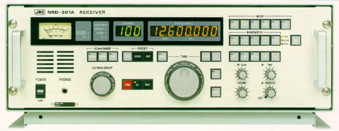
What kind of receiver is designed for professional use, 24 hours per day? What kind of receiver is designed for intuitive, non-fatiguing monitoring by shipboard radio operators? Such a receiver is the Japan Radio Company's NRD-301A. The display is large. The knobs are large. Each mode has a separate button. Each bandwidth has a separate button. There are separate knobs for RF Gain, Volume, Pass Band Shift and Squelch. This receiver is a dream to operate and is arguably the most impressive looking radio we have ever offered. And performance, as you would expect, is second to none. Many user defined functions are available to tailor the receivers operation to your requirements.
Coverage is 90.000 to 29999.999 kHz with 1 Hz display in LSB, USB, AM, CW, DSB (AM), FSK (RTTY) and FAX modes. Supplied bandwidths include: 6, 3 and .5 kHz (.3 and 1 kHz optional). The built in 300 channel memory stores: frequency, mode, bandwidth, AGC and ATT data. Scan and sweep are supported. Other refinements include: AF Filter, NB, Lock, Dimmer, Self-Test, AGC selection and front-firing built-in speaker. A built in self-test function is also featured.
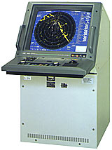
The NRD-301A is designed for mounting in a standard 19 inch commercial rack. It is shown above in its optional MPBX10832 desktop cabinet.
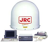
Japan Radio is a the leading manufacturer of integrated bridge, radar and Inmarsat equipment for the commercial maritime industry. To learn the full story on this most impressive radio, please request the color brochure with full specifications. This item is not available for online ordering. Please call.
Frequency Range ..... 90 - 29.999999 kHz
Power ............... 100/110/115/220/230/240 VAC 50/60 Hz
                      or 24 VDC 36 W.
Antenna Impedance ... 50 ohm
Selectivity (-6dB) .. 6.0 kHz
                      3.0 kHz
                      0.5 kHz
                      1.0 kHz [Optional]
                      0.3 kHz [Optional]
Sensitivity ......... 2µV SSB 1.8-30 MHz  (10 dB S+N/N)
Stability ........... ± 20 Hz after 1 min below 13 MHz.
                      ± 50 Hz after 1 min >  13 MHz.
IF Rejection ........ > 80 dB
Image Rejection ..... > 70 dB
Other Spurious ...... > 70 dB
Audio Output ........ 1 Watts at 8 Ohms
Standard Steps ...... 1 Hz, 10 Hz, 100 Hz, 1 kHz
                      5 kHz, 9 kHz, 10 kHz or 100 kHz.
RF Attenuator ....... 20 dB
BFO Range ........... ± 9.999 kHz (1 Hz steps)
Clarifier Range ..... ±  200 Hz (1 Hz steps)
Audio Output ........ 1 watt internal speaker
                      1 watt external speaker 8 ohm
                      10 mW or more headphone 600 ohm
Line Output ......... ± 10 dB (600 ohm balanced)
Circuit Type ........ Up Conversion Dual Superheterodyne
Temperature ......... -10° to 50°C
Dimensions .......... 19 x 7.5 x 12 inches (480x150x290 mm)
Weight .............. 16.5 Lbs. net (7.5 kg)
|
| Order # | Photo | Item | Description | List Price |
|---|---|---|---|---|
| #0193 | 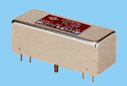 |
CFL-231 | This 300 Hz crystal filter provides razor-sharp CW reception. [YF455FMB] | $154.00 |
| #0294 | |
CFL-233 | This 1000 Hz filter provides sharp SSB and narrow shifted RTTY signals. [YF455DE] | $154.00 |
| #3675 | MPBX10832 | Heavy table-top cabinet The price indicated is if ordered with receiver (more if ordered separately). |
$499.00 | |
| #3675 | 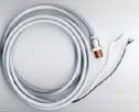 |
MPKC01741 | DC Cord | $ 34.00 |
| #2096 | 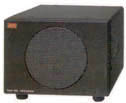 |
NVA-92L | External speaker with impedance matching transformer and cable. Does not match the radio in design or color. Must be ordered the same time as the radio. | $199.95 |
| #0682 |  |
ST-3 | Quality communications headphones. Well padded, great sound and 1/4 inch mono plug. | $ 77.00 |
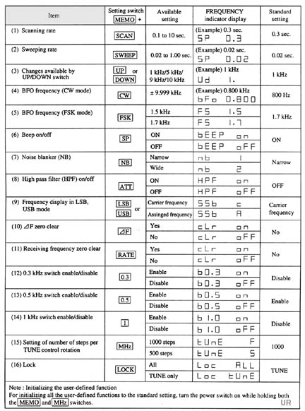
The Japan Radio NRD-301A has many parameters which may be user
defined. Please see the table above.
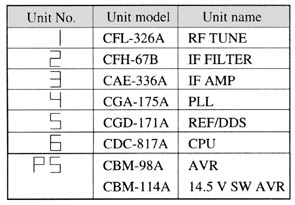
The Japan Radio NRD-301A features a built in test capability (B.I.T.E.). To activate this fature press the [MEMO] and [DIM] switches simultaniously. As long as the self test is active the frequency display will the indicate the number of the board being tested. See the table above. When all the boards have been successfully tested, a "Good" indication will be displayed for two seconds.
To return to normal operation, press any switch.
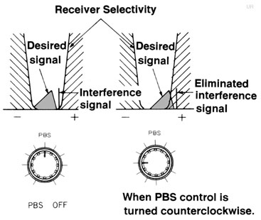
The JRC Passband Shift allows you to change the center frequency of the IF filter (± 2.0 kHz, with 6 kHz filter) with no apparent change in the reception frequency. PBS acts to set the offensive adjacent signal out of the receiver's passband. When the NRD-301A PBS knob is centered this function is off. As soon as the knob is taken off center, the PBS indicator lights and the function is activated.
In the USB mode, disturbance signals can be removed from the higher of the voice signals when this control is turned counterclockwise from the center position. Note that the high area of the desired signal will be cut off at this time. In the LSB mode, the reverse is true.
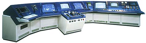
radar and Inmarsat
http://www.universal-radio.com/catalog/commrxvr/3673.html ¿¡¼ ¿Å°Ü Àû¾ú½À´Ï´Ù.
N9EWO report
The NRD-301A is no longer sold new. A mixed bag for this kind of money, but overall is built to JRC high standards.
(picture by DaveZ)
(Note: I'm not a current owner of a NRD-301A. Was able to use a sample for a test peroid.)
Discontinued Receiver (no longer sold
new)
Being a previous owner of a JRC-NRD-93, you
will see references to this model in the text below.
The first item that
hit me be about his JRC receiver of the 90¡¯s when I discovered that it existed
was the fact that it does not include a keyboard for entry of frequencies. After
a bit of thinking about this it does not make the set any more difficult to use,
after all it is marketed for the maritime/commerical market. The encoder that is
used for the Mhz/Memory Channel on this NRD-301A worked to my liking and has a
good feel to it, once in a great awhile it will skip a beat if you turn it slow,
that is it will take 2 clicks for a 1 MHz advance. Or it will go backwards, one
click up, it goes one MHz down. Seems not to be a optical encoder being used
here ?
Cabinet construction is almost a dead ringer to the NRD-93
(optional cabinet included). Pretty much all aluminum, with the outer Green
optional cabinet being a die-cast alloy of some kind.
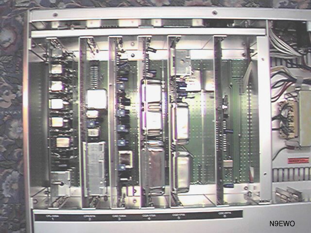
The PC Board quality and part placement is as good as it can get. First rate. (picture by DaveZ)
A note about the antenna
connections on many JRC receivers. The female ITK SO-239 connector found on the
NRD-301A and the NRD-93 are of a strange metric thread. Many (if not most) USA
style male PL259 connectors/adapters will not fit correctly. You might get it
started but never tightened. And you risk cross threading it if you force it. So
the best idea, is to use the male PL-259 that JRC supplies with these radios
(marked as M-P-5), Antenna Connector...you may say with the accessories... well
that¡¯s so common..so why did they include this....ah.not as common as you might
think ?? Save it ,praise it, and put it to use as you may not come across
another one.
JRC continued to use the weird HRS ¡°AC¡± power plug/socket
for interfacing the AC current to this set (see picture) . This has not changed
from the NRD-93 which uses this very same arrangement. This is a good durable
system with that locking ring, but finding a replacement plug from a more local
source other then from a JRC dealer is going to be almost impossible. I would
have like to seen a standard ¡°Computer¡± style power socket here, as found on
JRC¡¯s consumer sets. But maybe that¡¯s too far away from the commercial side ??
But a 3 wire power cord/plug is actually needed (see below).
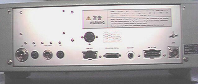
Rear View of the NRD-301A. Still using a few strange connectors. (picture by DaveZ)
You need to really ground
this receiver. Most of the time you think of grounding as it might help to
enhance the antenna system, but in the case if the NRD-301A it¡¯s for safety
concerns. You are dealing with a somewhat Hot chassis when powering with AC
current. The NRD-93 also has this same little buzz feeling to the cabinet that
can knock you off your feet if you are touching something else
grounded.
It is caused by 2 disc ceramic capacitors connected across the
rear of the AC input socket inside the set and then connected to ground on the
case of the set (marked as C1/C2 on the Chassis Schematic). Solutions: The
easiest cure is just to ground the set correctly or second: removal of these 2
capacitors. These are not required for correct operation of the set. They are
used for RF bypass when the set is being used with a transmitter. As most Short
Wave Listeners are not going to use a transmitter with this receiver in its life
time, just removing these will do no harm. But grounding the set correctly will
completely clear up this stray AC current from the chassis.
The selection
of the correct AC Input voltage is very much improved. You just have a rotating
disc on the rear panel that selects the proper voltage for your country (with
the set off of course). This may not sound like a big deal....but on the NRD-93
it was a hard wired affair. That is you needed a soldering iron and about a half
an hour to make the change.
Operation of this set is very much on the
HOT side. This is due to the Consumer Quality power transformer used in the set
(see picture). It has no shielding, make a fairly noisy buzzing sound when
loaded down (probably due to the lack of proper coating of the windings ??), and
after say an hour..this transformer reaches a temperature that you simply do not
want to place even a finger on it, it gets that hot. This is a part of the set
that I was not happy about at all !! The power transformer that was found in the
NRD-93 was of very high quality, shielded, made no noise, and only got mildly
warm. The voltage regulation circuits in the NRD-93 were the heat maker in that
set, the total opposite in the 301A.
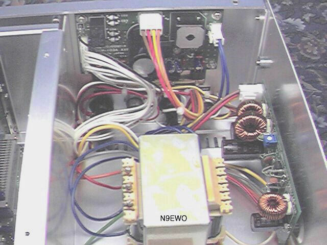
Power Supply Section: with it's poor quality power transformer. (picture by DaveZ)
Both of these sets use
switching power supplies, however I do not hear these bothering the receiver, at
least of any concern, unless what I have in the next paragraph might be
involved??
However there is another noise that exists , and is not a new
one for JRC. The NRD-93 has a sound that I have never heard emitting from a
radio. It¡¯s a very high pitched whine. It will get louder as you turn up the LED
display brightness control. This sound seems to be coming from the power supply
part of the set. This also is where part of the circuit is for the LED
brightness control is as well. JRC has continued to use a similar circuit in the
NRD-301A. It too whines the same way, and increases in pitch and volume as you
push the Dim button to brighter display. This seems to bother some people but
not others, depending how good your hearing is. It drove me up the wall, and was
one of the main reasons why I did not keep my NRD-93.
This whine never
enters into the receiver or audio chain of the radio, but it sure does fill the
room up with this sound of those who can detect it..
The general layout
of the 301A was very pleasing to me. Nice BIG LED digits for frequency and
channel display, with 4 step dimmer. The continuos dimmer knob on the NRD-93 is
more preferred, but the step button gets the job done. I prefer LED¡¯s, because
of long life and easy on the eyes. The lack of a light on the S-meter is a
disappointment, be this rules out having to change the lamp down the road after
it burns out (as just about all panel lamps need to be changed sooner or
later).
I do miss the green LED PBS display that the NRD-93 has. I gives
you a reference of where you have the control set excactly, and can return to
the same spot again.
No play in the tuning knob, either side to side or
in and out...great to see this. This tuning knob does have a way to adjust the
rotating torque. This is done by loosening the set screws on the knob and
sliding the knob closer or further on the encoder shaft. The knob is pretty
stiff as it comes stock.
Above average grade of sealed variable controls
are being used, as was on the NRD-93. I found the small knobs being used for
volume/RF Gain etc..were a bit small for my liking. The NRD-93 wins here.
Spacing of the volume/rf gain/squelch/PBS knobs was also a bit tight to me as
compared to the 93 (with the bottom and top rows being too close
together).
I could not tell for sure what type of encoder was used for
tuning (knob). The schematic gave information that was incomplete. It should be
of a optical quality ? A peer inside at the encoder itself still does not give
enough information. Marked on the encoder: Manual Encoder MKE-005-2 Nemicon
Corp, Toyko , almost makes you think that it NOT optical ? But it never skipped
a beat, so I'm guessing that it has to be optical ??
The tuning knob can
be selected for different rates. The NRD-93 had only one fairly slow tuning knob
rate, which I did not care for. Band scanning with the tuning knob was very slow
for me on the 93, even with the slewing up-down buttons right next to it. So the
arrangement on the NRD-301A (as it is on the NRD-545), where you may select many
different rates of the main tuning knob is a huge improvement for my
tastes.
The RF Gain control takes a bit of getting used to. When adjusted
it has a step type sound. That is it adjusts in steps. A study of the schematic
indicates that the control is tied into the main CPU for adjustment. First set
for me to see a digital adjustment for the RF Gain.
The speaker and line
outputs always bothered me on the NRD-93. The main speaker output was at 600
ohms, and used a isolation transformer before it seen the output jack (however a
4 ohm was available at the rear), another small 600 to 8 ohm audio transformer
was installed inside the external speaker for matching. This has been improved
to a more traditional standard in the 301A with all being at 8 ohms, and
standard plug on the rear panel and no isolation transformers. The 600 ohm
balanced line output continues to use a matching transformer.
However,
other connections continue to be via the very strange so called BK (Break)
connector (see picture), that is Line Audio output, other speaker connections
and muting. As for the line connections, for a correct connection, the 301A's
output which is at a Balanced 600 ohms..to properly match to consumer
equipment..a external transformer (forget the ones that radioshack sells ...too
small and light...been there done that) should be used to approach the 30K~50K
ohms unbalanced line inputs that is used for most consumer tape equipment. Mind
you it will work the way it is...however the audio quality might suffer a bit
due to impedance mismatch. But the correct audio transformer might cost around $
100, for a Good broadcast quality one. So give it a try without.
Tip:
Using a standard shelided audio cable...Use one connection of this 600 ohm
"Line" for the center conductor of the cable and shieled to the other. However
try and use a jumper wire to connect the "shieled" to chassis ground. Of course
ground loops can sometimes happen messing around with Balanced stuff, but try it
this way and see what happens. This also goes for the NRD-93 and the WJ HF-1000
/ WJ-8711A along with others that are using a balanced output.
The
NRD-301A has a similar trait that I also noticed on the NRD-545. On many AM
(DSB) signals that have low modulation ..it sort of runs out of volume control.
That is I have to turn the volume control up well past 12 o¡¯clock to even start
to hear the signal. On any SSB or normal AM signal you never notice
this.
Sensitivity is a definite improvement over the NRD-93. How much ..I
cannot say, But I could tell only after 30 mins of operation that this set is
better. The NRD-93 was good, but not in the Excellent/Superb category. Both of
the sets are using a dual-conversion scheme.
The audio quality of the
NRD-301A : I will have to say that it is average, that is not really that good
or poor. More distortion than I would like to see in a receiver , and comes no
where close to the AR7030 in the audio department..
You must watch the
adjustment of the RF Gain control on this set. The NRD-93 was also in this same
situation. However , it is even more important on the 301A.
On AM mode
signals, I notice if you have the RF Gain up too far, distortion sets in very
quickly. Even ECSS mode operation suffers if you run the Gain control wide open.
The distortion level on SSB signals with the AGC in the Slow position is nil,
however in ¡°Fast¡±, distortion creeps in quickly and the RF Gain control has
little effect.
Operation of the NRD-93 with signals in the SSB mode and
using AGC Fast decay rate, sounded good with no distortion. But the Slow rate
was very SLOW (unusable matter of fact). So overall the arrangement on the
NRD-301A sounds better to me.
The two bandwidth filters that are
installed in this set for ¡°broadcast" (manual ECSS or other) listening, are
adequate. Adding any additional Voice Bandwidth filters (say a bit wider), is
always a problem as JRC does not offer any, and other people who do..most of the
time the radio has to be modified in order to use them. It¡¯s not just a simple
solder in affair. I feel it does need another, bit wider voice bandwidth filter
(but that's me).
In conclusion, the NRD-301A is a set that keeps the
tradition of JRC alive in the High end commercial market, however for my needs
and likes it simply does not show enough features and quality (major power
transformer flaws to name one) plus its steep price tag to make me run out a
purchase one. In general it's internal board construction and overall quality is
no different then JRC's lower cost receivers . The metal front panel and above
quality rotary controls are of a higher standing.
To us comsumer types
this set is already Long in the Tooth (old stuff) as compared to the newer DSP
sets, even it's NRD-545 actually outperforms it (filter wise) at less than half
the price (at time of writing).
N9EWO
(Discontinued
receiver)